Building a Homelab, Part I
The Hardware
Posted on 2024-01-02
It’s that time of year when it’s easier to justify splurging on tech I don’t really need because of my birthday, holidays, anniversaries, mid-life crisis – you name it. This year I decided to build myself a proper little homelab, a considerable upgrade over my low-power Ryzen server.
As raison d’être for the homelab I settled on virtualisation. It will be running self-hosted services like Pihole and Octoprint. To spice things up, I’m going to use Ganeti to manage my cluster. Ganeti is an open-source VM cluster management tool by Google which supports VM replication and live migration, a topic I’ve been fascinated with for some time. Time permitting, I might even try Ceph for distributed storage.
This is going to be a series of posts covering different aspects of the project. Right now, in my head, it looks like this:
- The Hardware (this post)
- Network Boot with iPXE and Mikrotik (and containers and stuff)
- Declarative Provisioning with NixOS
- Setting up a Ganeti cluster with Ceph
- ?
But I’m getting ahead of myself. I want to point out that the biggest ROI here is learning opportunity. There is no palpable end goal – just a general direction.
Let’s get started with choosing and building the hardware.
The Servers
A while ago I stumbled upon this STH article on using refurbished all-in-one PCs as servers. I really dig the idea – these small servers are quiet, inexpensive, with parts that can be replaced, and some even come with a Windows license. Often used for lightweight desktop workloads like editing documents and browsing, they are usually in mint condition. There’s a big market for these PCs: firms sell large quantities when they go under, or simply decide to refresh their hardware stock. And there are folks that buy these at auctions, refurbish them and sell them to other firms, or individuals like me. Therefore, I was able to find loads of offers on eBay, with plenty of variety. Most of them let you choose CPU, amount of RAM and storage, and had more than one unit available for order.
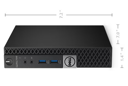
After a bit of browsing, I found a really good one: 4 x Dell Optiplex 7040 Micro (product page), equipped with a quad-core Intel i5 CPU1, 32GB RAM, 500GB SSD and a 2.5 inch 500GB HDD. All this for £189.99 a piece! Given that I was making my first such purchase, I wasn’t really sure if I should order fewer units first, and then order more after checking what state they were in. But I ultimately decided to make a leap of faith and ordered four.
I was quite impressed with how well PCs were packaged. Each came neatly packed in its own box, sealed in an anti-static bag, with a power adapter and a small SMA antenna for WiFi. Even though seller mentions that refurbished PCs might have some visual damage on the case, like scratch marks, I did not find any. All four PCs looked brand new!
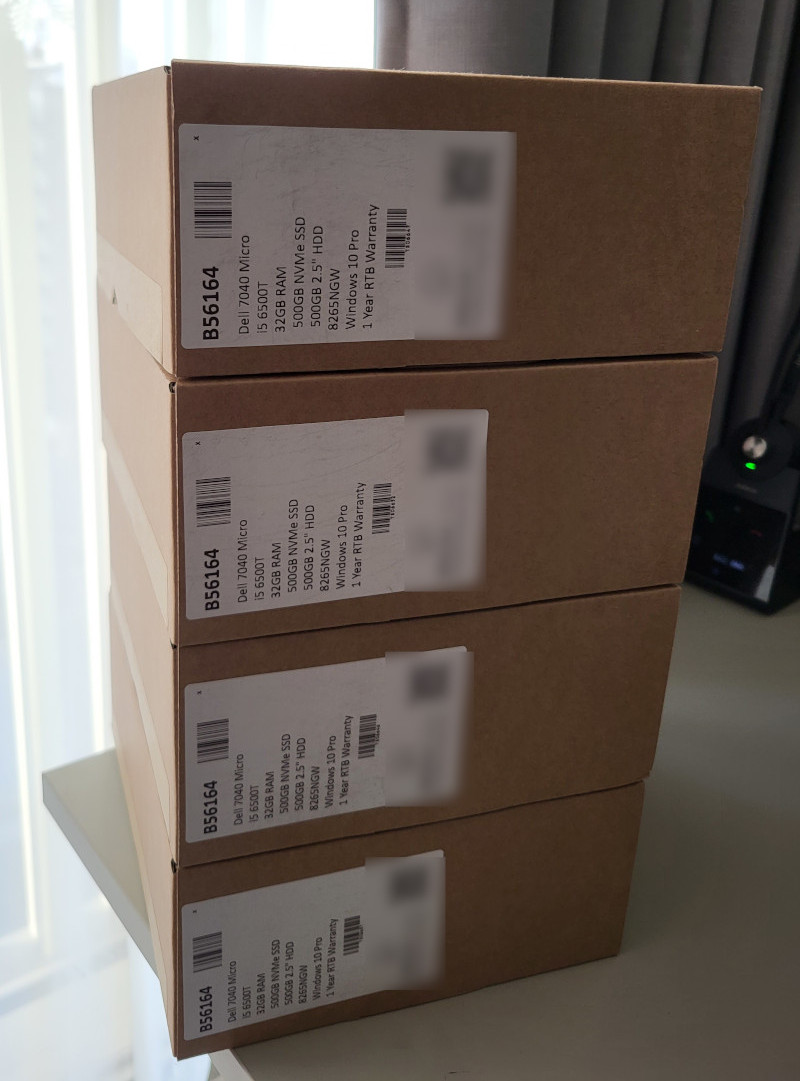
Each PC came with a Windows 10 Pro license, which might come in handy if I ever need to use one of these as a desktop PC.
On Server Racks
I knew next to nothing about server racks before I delved deeper, other than people use them to host hardware in datacenters. I did a little research and found out that racks are little more than a set of sturdy vertical metal rails, with holes punched at even intervals, and some enclosing.
There is a standard that defines width and height of hardware, i.e. rack units (RU), that are installed2. Unit height, or 1U, is 44.5mm. Unit width can be either 19-inch (482.60 mm) or 10-inch (254 mm), with 19-inch racks being prevalent in the industry. Due to their smaller size, 10-inch racks are popular in the homelab community. Unit depth can vary, from what I’ve seen.
Rack height refers to number of rack units they can hold. For example, 42U rack can host 42 units. Note that some hardware can be 2 or more units tall.
Smaller racks are sometimes called network cabinets, as they usually store routers and switches. They often have a front panel that can be closed, unlike most DC racks which are open. These cabinets can be, in most cases, mounted on walls because of their small weight. Their height ranges from 2U to 16U.
There is an entire family of rack accessories, of same unit dimensions as hardware, that provide various functionalities. Most notably, patch panels are used to label and organise network cables. A PDU, short for power distribution unit3, supplies power to other hardware in the rack. Other noteworthy accessories include fan panels, cable management panels4, and rack shelves. The last one is simply a shelf mounted in a 1U slot. It’s quite popular for homelabs because it allows one to simply place any piece of hardware on the shelf, in the rack, without much fuss.
It is a common practice for each rack to have at least 1 ToR (top-of-the-rack) switch, to which all devices in the rack are connected. This provides L2 connectivity within the rack. ToR switch is connected to the next layer of DC fibre, which extends to ToR switches in other racks, and all the way up to WAN.
The Cabinet
All right, based on what I had learned so far, and considering the kind and the number of servers I planned to install, I decided I should go with a 10-inch network cabinet. In addition to that, I was also going to need:
- a ToR switch
- a patch panel
- a PDU
Now, how big of a cabinet would I need? I sketched it out:
===== top =====
patch panel
switch
optiplex 7040
optiplex 7040
optiplex 7040
optiplex 7040
pdu
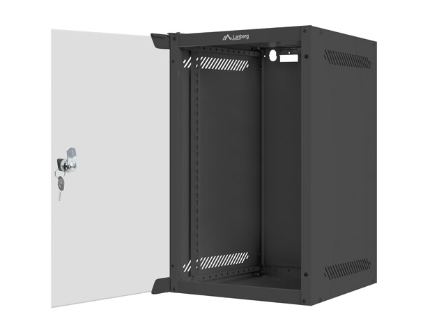
===============Rounding up to next widely available cabinet height, I started looking at 9U 10-inch cabs. Turns out matching products are very similar. In the end I opted for Lanberg WF10-2309-10B (product page) simply because it has an active cooling option. Most network cabinets aren’t designed with optimal airflow in mind because the kind of gear they usually host doesn’t get too hot. This cabinet was also decently priced at £50.
The PDU
I needed a PDU with five sockets to power 4 PCs and a switch. However, all 10-inch horizontal PDUs I found on Amazon either had two to three sockets, or had four EU-type sockets. I looked at how much clearing I had between the front glass door of the cab and front rails – I was definitely not going to be able to fit a UK-to-EU plug adapter on top of Optiplex power adapter. At that point I also realised I would need 2 PDUs to provide more than 4 sockets. Guess I will have to get a PoE-powered switch then.
I ultimately found a 4-way 10-inch UK PDU over at aptly named pduonline.co.uk.
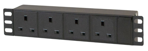
Priced at a whopping £46 with VAT and shipping, almost as much as the cabinet, this is one purchase I’m not particularly proud of. In hindsight, I could have well gotten away with a regular 4-way UK extension cord (about 10 quid) and a custom printed rack mount. This one does feel sturdier and matches the color of the cab, though. Note that it’s height is 1.5U, and while it doesn’t really use up an additional half unit height, it does cover up the lowest of three screw holes of the slot directly above.
The Switch
I wanted a dead simple, 5-port Gigabit non-managed switch that can be powered through PoE. I considered picking up an inexpensive MikroTik router, which provides far more control and L3 routing, but I didn’t want to have to manage another network device. Besides, from a purely aesthetic standpoint, most Mikrotik routers have white casings. I’d have to get a RouterBOARD and a custom case if I wanted it to go along nicely with my black cab, black Optiplexes and black PDU.
I actually had a hard time finding this. When you type PoE switches in Google, you usually find switches that provide PoE-out. That seems to be quite popular nowadays with PoE-powered CCTV and IoT devices. After some searching, I found Tenda TEG1105PD (product page). It even provides PoE-passthrough on 4 ports, should I ever need it for other purposes. This set me back £20, which I feel is a fair price.
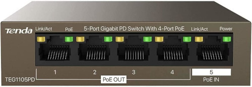
After it had arrived, I happily connected PoE-in port of the switch to PoE-out port of my MikroTik hAP ax3. Much to my chagrin, however, the switch did not power on. It turns out that the switch requires active PoE input of 50-57 V DC at 0.6 A, which means it needs a minimum of 30 W of power. This is clearly stated in the datasheet. Active PoE is standardised in IEEE 802.3af and IEEE 802.3at, and apparently includes a negotiation protocol between PSE (power-sourcing equipment, device that provides the power) and PD (powered device).
My hAP ax3, on the other hand, provides passive PoE5. Passive PoE is an umbrella term for any PoE implementation that does not adhere to IEEE standards. My router can provide a maximum of 15 W of power at 0.625 A, which sets maximum output voltage at 24 V.
Oh boy, at that point I realised I was going to need a PoE injector in order to power this switch. This made me question my decision not to go with MikroTik, because I know their cheaper routers can be powered through Passive PoE just fine. Resigning to sunk-cost fallacy, I ordered a Tenda PoE30G-AT (product page) injector, that provides 30W of power through active PoE 802.3at. That was an additional £15. After hooking it up, LED on the switch port lighted up, and all was good. At least the injector doesn’t have to be inside the cabinet.
The Patch Panel
Patch panels are rack accessories that have a specific number of incoming ports and outgoing ports. In most cases, these are ethernet/optical/coax ports. Incoming ethernet cables terminate at the rear end of the patch panel. Cable ends are stripped of insulation, wires are untwisted and lined up on a port terminal according to their color, and finally “punched down” using a tool that neatly trims off excess wire6.
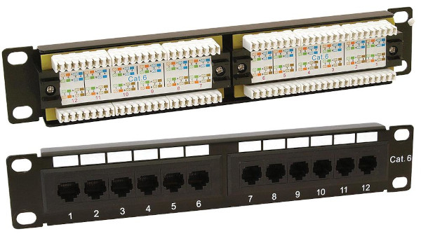
What’s the value, a careful reader might ask, of a panel that provides a simple pass-through? Patch panels act as switchboards. They make it easy to organise and label incoming cables, and to interconnect various devices inside the rack. Connecting a specific server to a different port on a switch is much easier with a patch panel. In addition, they also provide easy access to ports that are located on the rear end of the device, which is inaccessible in enclosed racks.
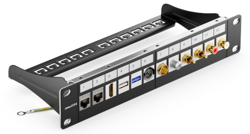
I’m not really a hands-y guy, and I shy away from any kind of work that involves precision. Luckily, keystone patch panels exist. To avoid the ordeal of terminating incoming cables at the panel, keystone patch panels provide port “holes”. You then pick a desired keystone module – for example, ethernet, USB or HDMI module – which is a simple pass-through enclosing. And then you just plug the module into a port hole on the panel. Voilà!
The thing I like the most about keystone patch panels is that you can mix and match keystone modules. They are a bit more pricier because you have to purchase modules separately. I picked up a deleyCON 12-port Modular Patch Panel (product page) for £19, and a set of 8 Cat6 shielded keystone modules for additional £24, both on Amazon.
Given cabinet’s physical dimensions, I also ordered 4 x 50 cm ethernet cables to connect Optiplexes to the patch panel, 5 x 15 cm ethernet cables to connect the front of the patch panel to the switch, and one longer 3m ethernet cable to connect the switch and the PoE injector (which is currently sitting next to my router).
Finally, I ordered 4 HDMI keystone modules and 4 x 50 cm HDMI cables to connect Optiplexes’ HDMI outputs to the patch panel. This is going to be useful if I need video output7. Optiplexes already have 2 USB ports on the front side that are going to be easily accessible when they are racked in, so there’s no need for any USB keystone modules. I also got some keystone blanking plates to cover unused keystone slots.
I ordered all of this from AliExpress – if you aren’t in a hurry, this is going to be cheaper, and likely of the same quality, as stuff from Amazon. All in all, cables, HDMI keystone modules and blanking plates cost £54, tax and shipping included. I did make several orders, though, so it would have been cheaper if I had bundled it all in one. And much cheaper if I had bought a 10-meter ethernet cable and RJ45 connectors and manually cut and crimped it.
Rack Mounts
There was one missing piece to the puzzle: how do I rack the servers? Both the PDU and the patch panel have rack mounts on either side, as both are made to fit in 10-inch racks. This is not the case with Optiplex PCs – they are meant to be laid horizontally or vertically on a desk, or VESA-mounted on the back of a monitor.
I found a shop on Etsy that sells 3D printed 10-inch rack mounts for common homelab equipment, including Optiplex 7000 series PCs. However, I couldn’t justify the price – it didn’t really align with what I’d spent on hardware.
I could have ordered 4 rack shelves and used those, but I really wanted this setup to look like a proper rack.
It just so happened that my wife got a Elegoo Neptune 3 Pro 3D printer for her birthday. It was very endearing to see her feed all sorts of STL files she could find on the net to the printer, and then marvel at results. That thing has been working almost non-stop during the past quarter. On the other hand, I wasn’t interested in trying it out. I didn’t think much about 3D printers, and waived them off as gimmicks that can produce bespoke headphone holders, plant pots, or DnD props.
But after I had found out someone made a business of printing 3D rack mounts, which looked very sturdy and professional at that, I knew I had to give it a try. So I looked for existing 3D models of 10-inch rack, and I found this one by DutchDeveloper. I love that honeycomb mesh design! Unfortunately, the mount is supposed to be installed in a 19-inch rack, side by side with another Optiplex mount8.
Since I wasn’t able to find any 10-inch STL designs, I decided to try and build something similar to DutchDeveloper’s model above. I never used CAD tools before, so I sit through Free CAD For Beginners tutorial from MakeWithTech@. It has 3 quick lessons, and it taught me pretty much everything I needed to know to design my first model. I foolishly thought I’d be able to import DD’s STL file into FreeCAD and then tweak it to my needs. But STL files only contain surface data. So I had to start from scratch, and use the STL file as reference.
I decided to start with rack mount for the Tenda switch first, because the switch is smaller and lighter than an Optiplex. I was able to use precise measures for front panel dimensions and hole positioning and size thanks to the schematic I mentioned earlier. Here’s my first try:
Following my wife’s advice, I adopted a prototyping approach she was very familiar with. I would abort the print job after 10 to 15 minutes, and then check if size of the hole fits the router. Then I’d tweak the model and try again. This would continue until I was happy with the dimensions, in which case I’d let the next print job finish.
And this is how the full print came out:
I learned the hard way that I have to take care not to make any structure too thin with 3D printers. I also made the case too thick, which made it hard to squeeze the switch in, and too long, so there was some empty space after I pushed the switch all the way in. Lastly, the front panel was too thick, and was not flush with the patch panel.
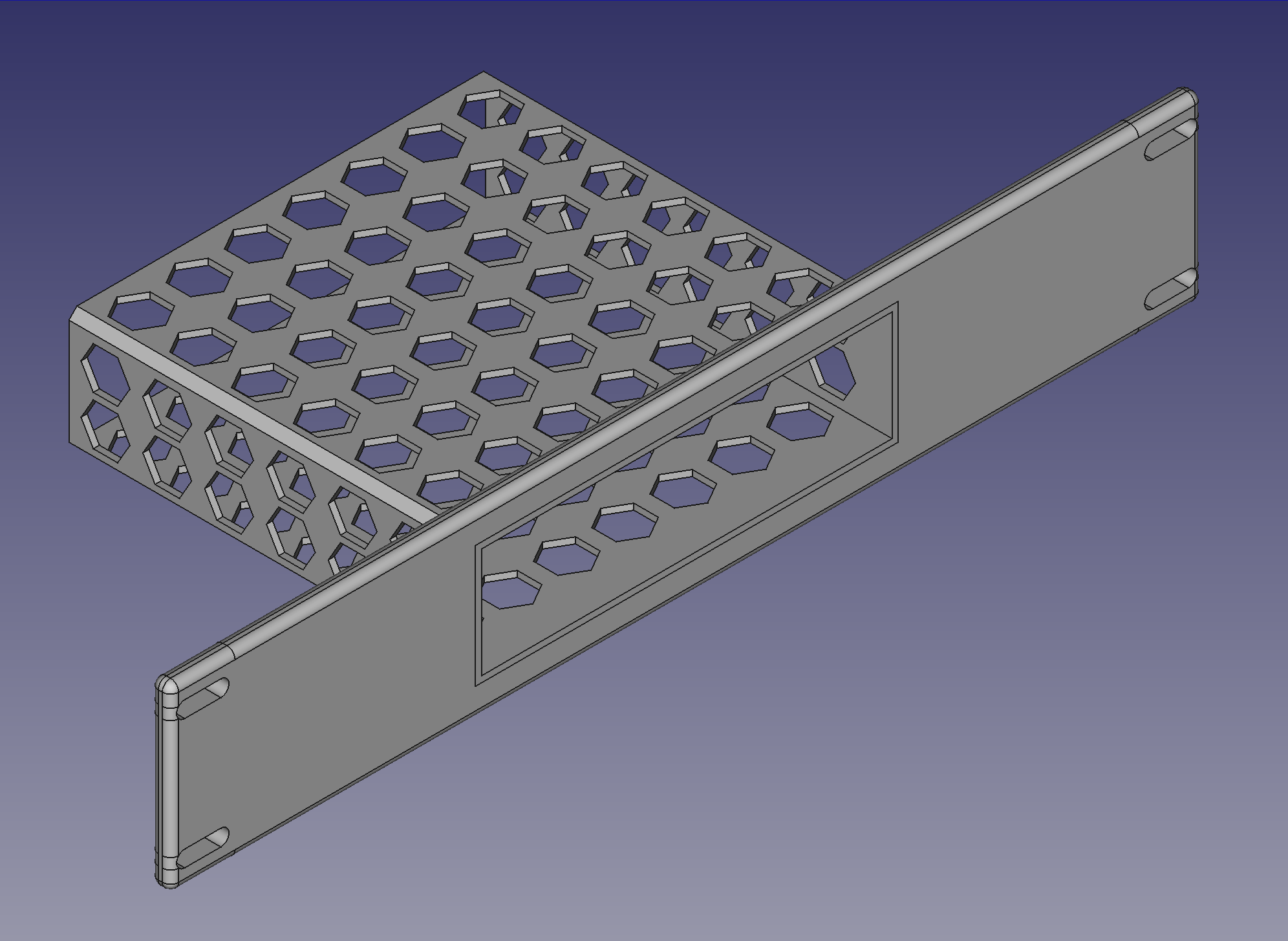
I did a couple of more iterations, tweaking front panel width, casing thickness and gaps between holes in the pattern. In the meantime, I found this honeycomb pattern FreeCAD tutorial. Things just clicked after reading through that one. I also learned how to clean up my design layout, use appropriate constraints, share dimensions between sketches with references, minimise dependencies between sketches etc. Here’s the final iteration of my Tenda rack mount design:
Small holes on the rear side are for securing the switch with zip ties, even though it fits snugly in the case.
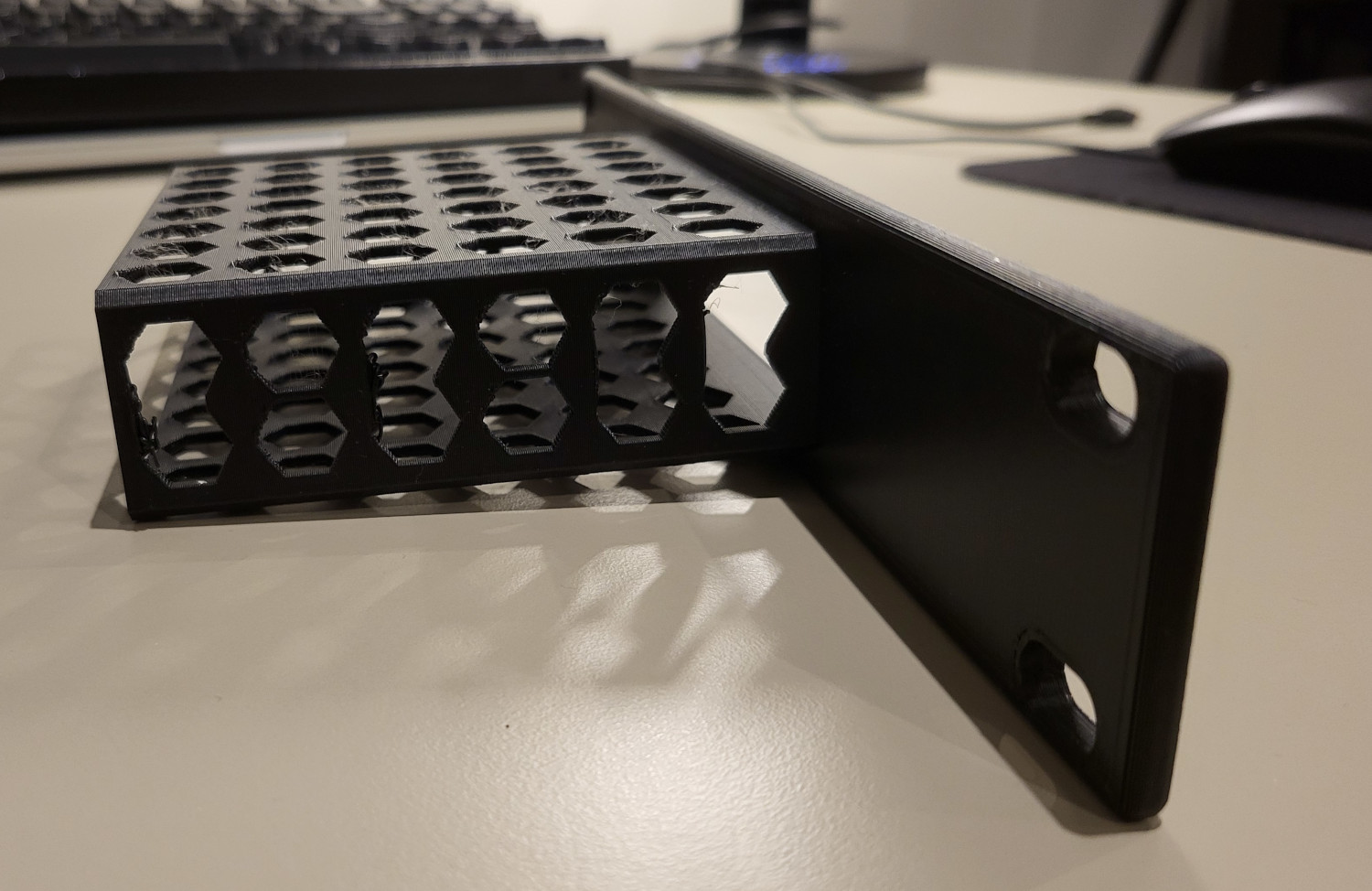
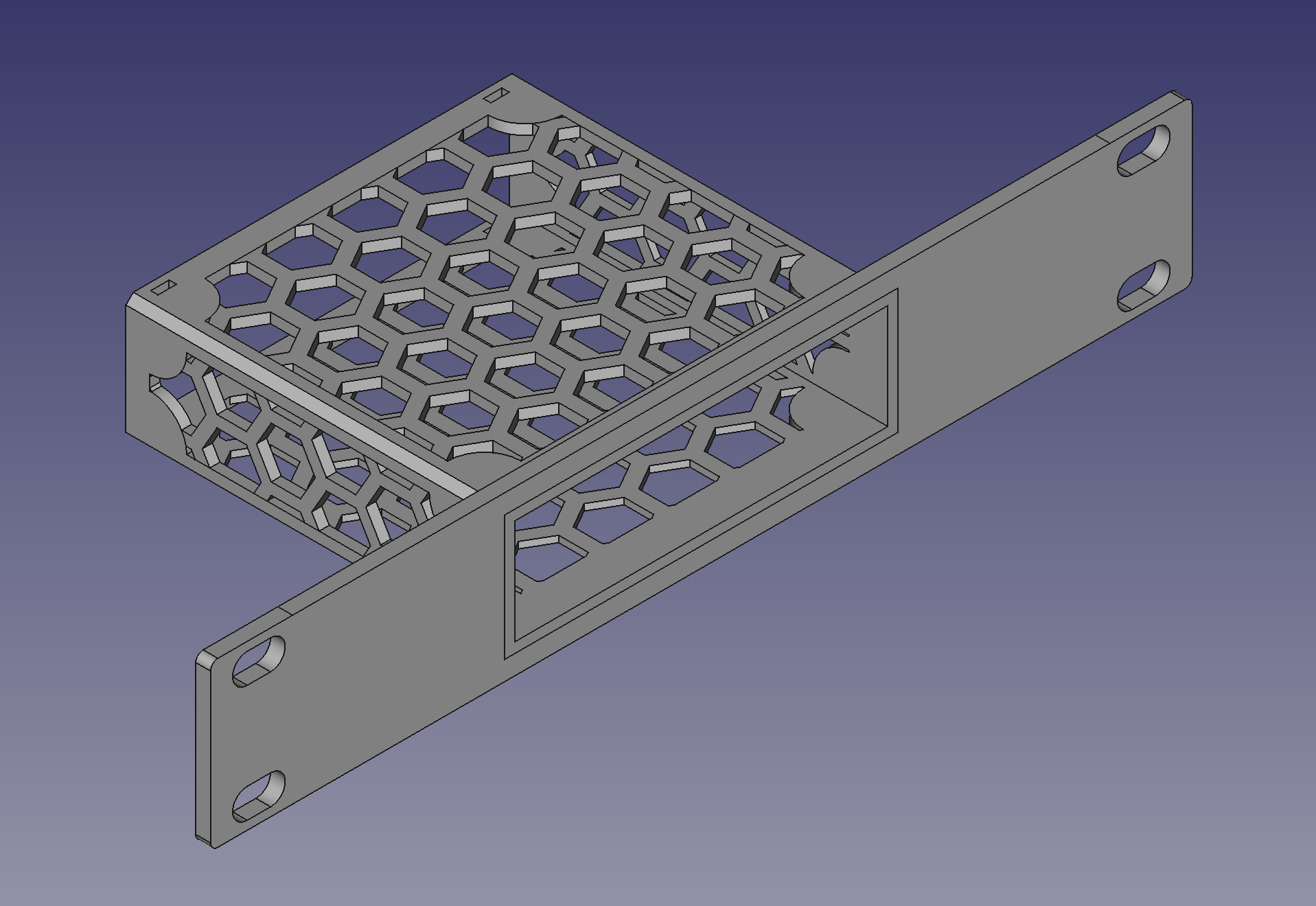
Now I felt ready for the Optiplex mount. I won’t hide the fact that my work is very much inspired by DutchDeveloper’s model, including the front lip to stop the PC from moving forward. I am proud to say my original contribution is the ledge on the left hand side, for the power adapter to rest on.
I again made the first version too thin. The top side literally tore apart when I tried to secure zip ties at the back. After seven iterations, the mount was good to go.
Here’s how it looks fully loaded and ready to be racked:
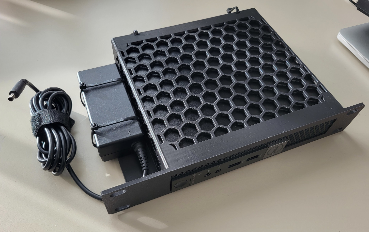
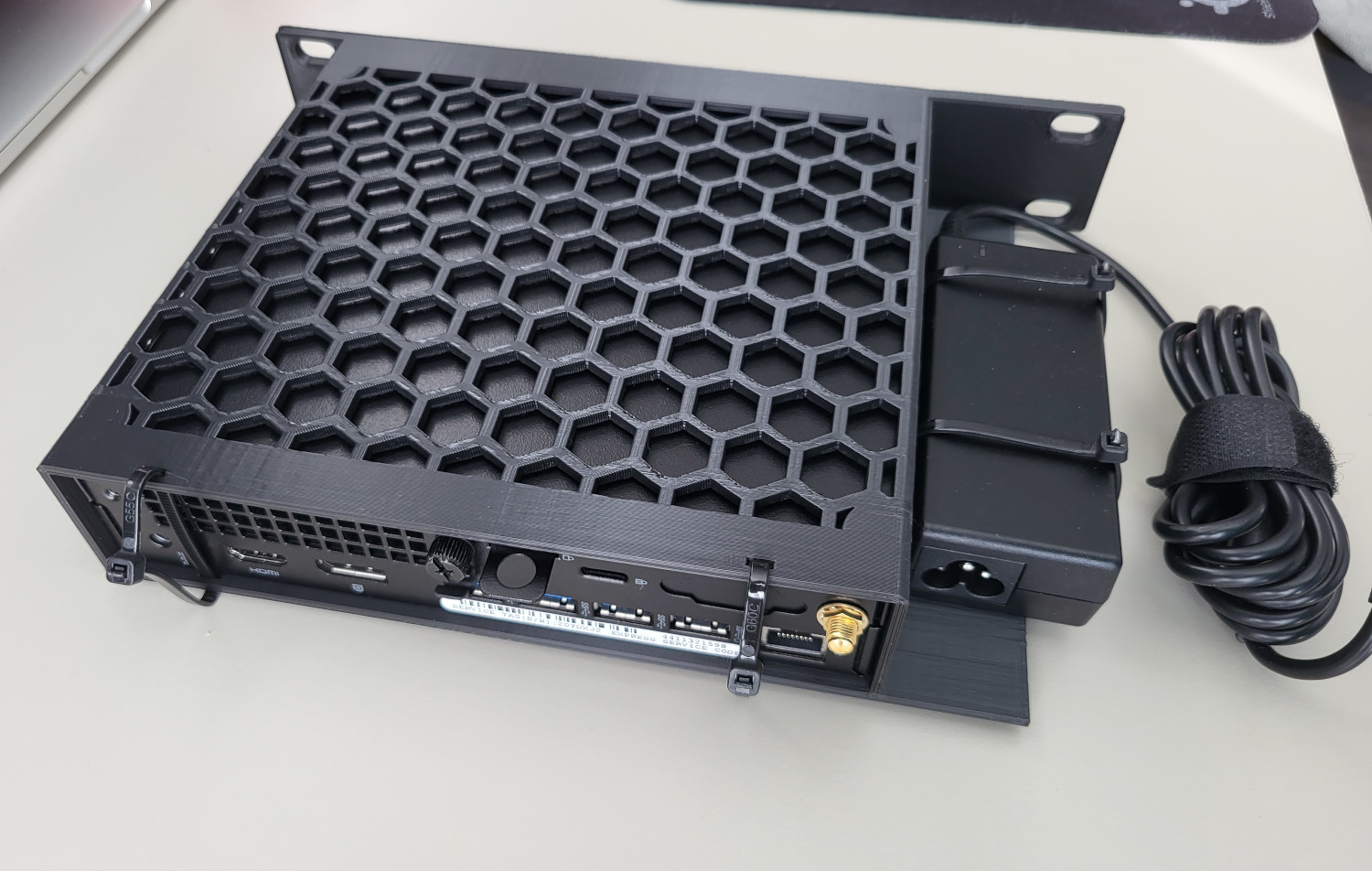
Note: we had to remove non-slip rubber pads extruding from the bottom side of Optiplexes before we slid them in the mount. This is easily done with a set of pliers.
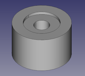
Since I was now obviously an expert in 3D modelling, I also made some legs that fit the cab. This makes some room between the bottom side and the floor for PDU power lead and the PoE ethernet cable (the one that powers the switch) to go through. The legs are secured with 35 mm M10 screws to existing holes on the bottom side of the cab.
You can find design files, made with FreeCAD 0.21.1, and exported mesh files for all designs below.
| Model description | Design | Mesh |
|---|---|---|
| 10-inch Dell Optiplex 7040 Micro rack mount | FCStd | STL |
| 10-inch Tenda TEG1105PD rack mount | FCStd | STL |
| Leg for Lanberg WF10-2309-10B | FCStd | STL |
| Leg for WF10-2309-10B with bottom hinge cutout | FCStd | STL |
We used regular Elegoo PLA filament for printing. I estimate we burned through much less than 2 kg of it, including all prototyping prints and final rack mount and leg prints, but I’ll round it up just in case. Price for that amount of PLA is around £20.
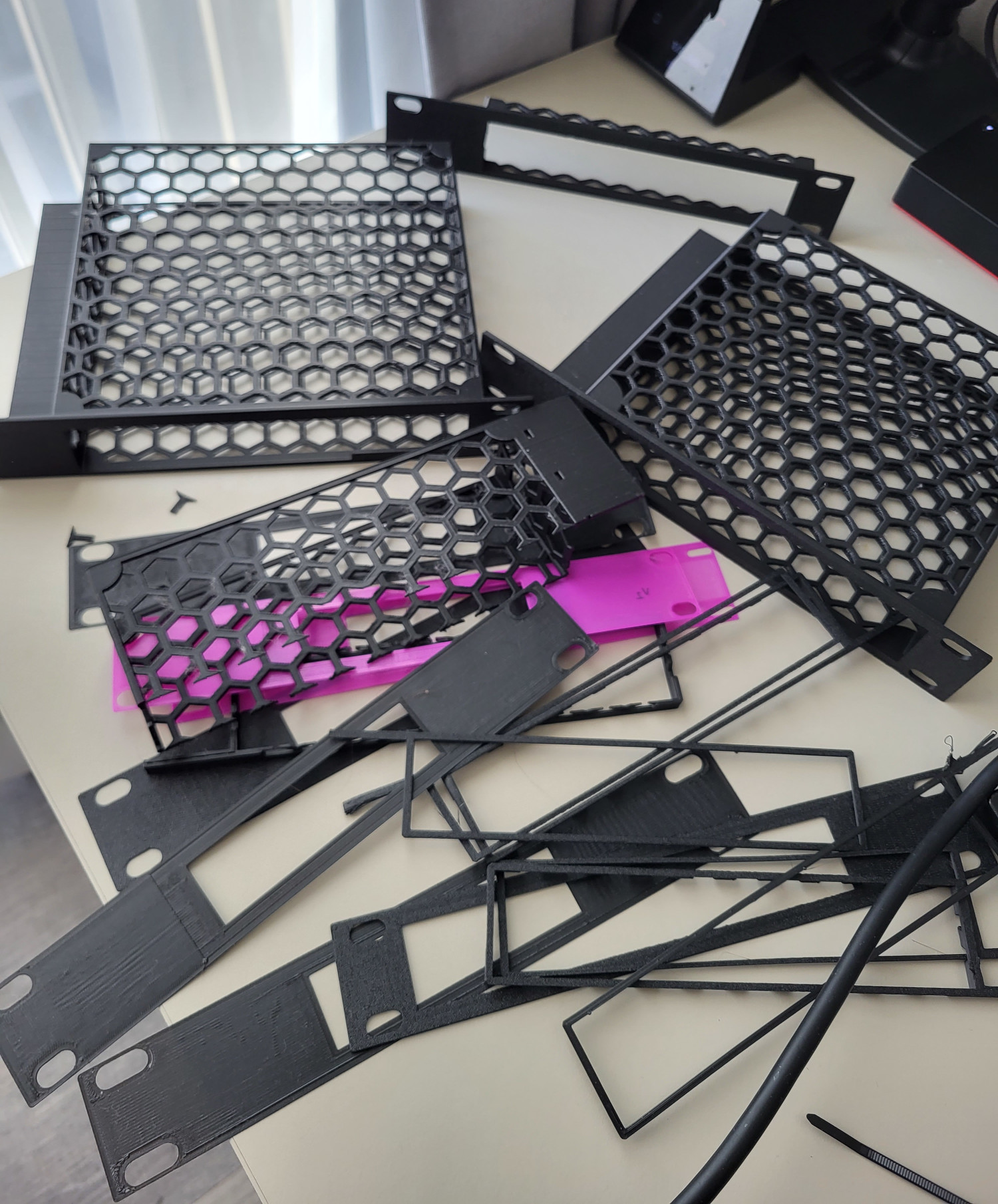
To wrap up this section, here’s a collection of throwaway prototypes I printed.
Assembly
Now I only had to put it all together.
Cabinet assembly instructions were easy to follow. Unfortunately, I found quality of parts lacking. Often times screw holes on side metal sheets did not align with holes on top and bottom metal sheets, to the point where some of the screws had to go in at an angle. In other places, if I tightened the screws too much, sheets would visibly warp. I had difficulties seating the glass door so it can swivel on top and bottom door hinges. But in the end I managed to make everything fit.
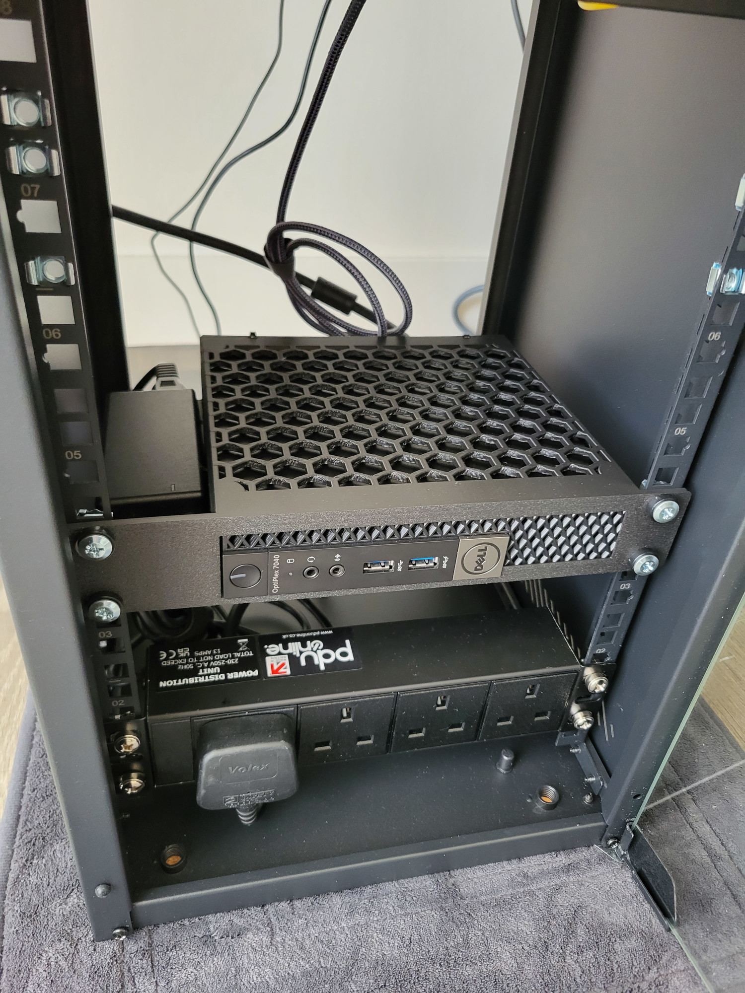
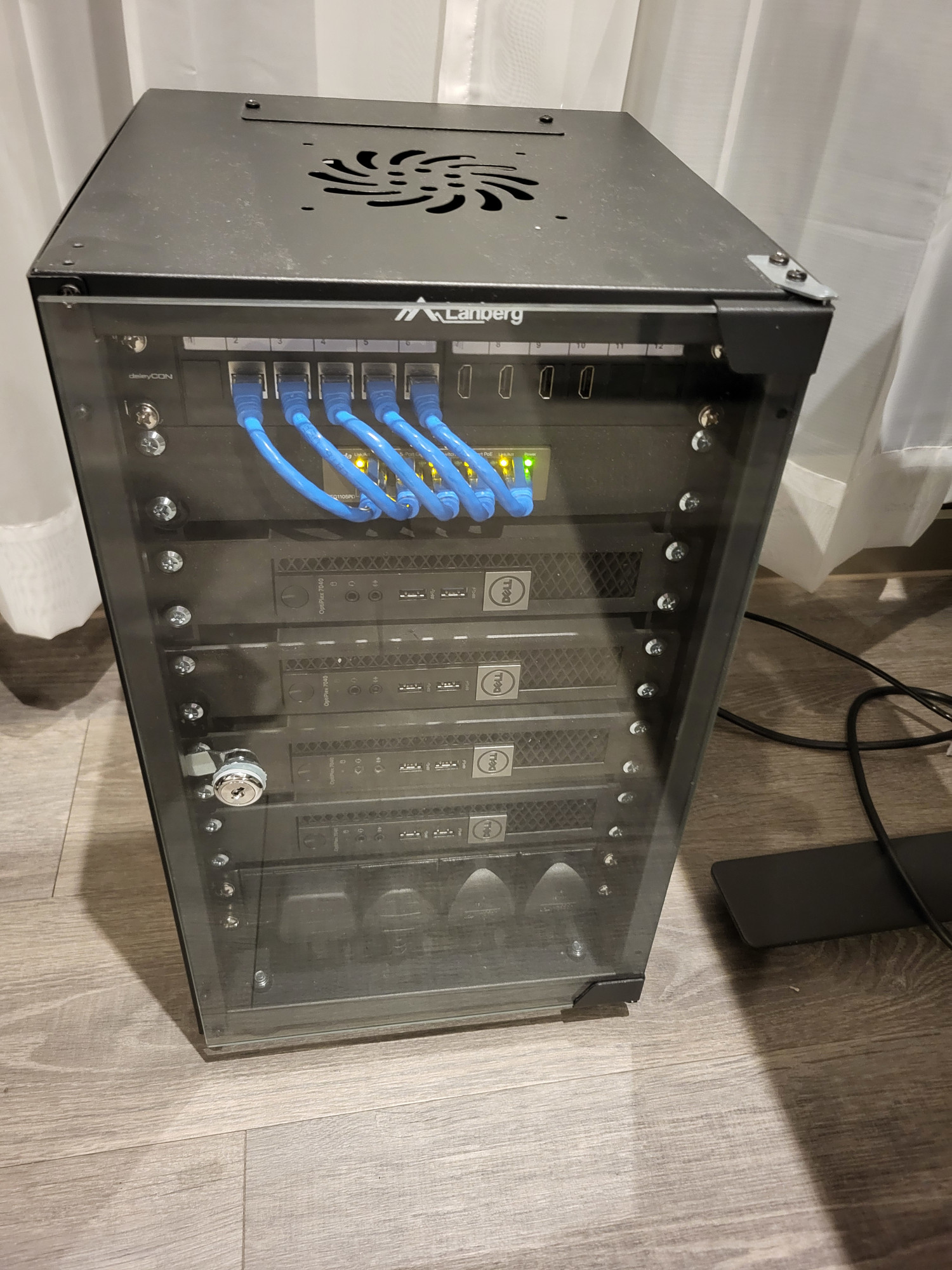
This is how it looked after racking patch panel, PDU and one Optiplex – I hadn’t printed any legs by this point. I had also left the rear side of the cabinet open until I put everything in, and closed it up at the very end.
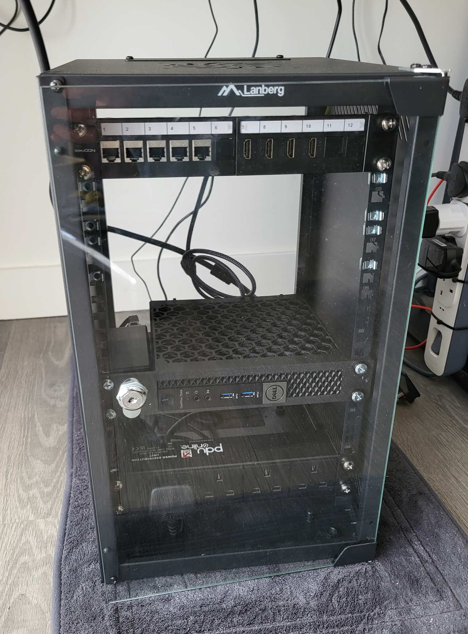
Next, I installed remaining Optiplexes and the switch. Given that I had some leftover room, I decided to leave a 1/3U gap in between Optiplexes. I am still not sure how hot it’s going to get in there, so it’s probably better if there’s at least some room for the air to move freely.
I then connected the switch to the front of the patch panel, and each Optiplex to the back of the patch panel, with both ethernet and HDMI cables. Ethernet cables at the front ended up being a tad too long. They push away the front door slightly. Luckily, locking the door counteracts that. Finally, I printed and installed the legs as well.
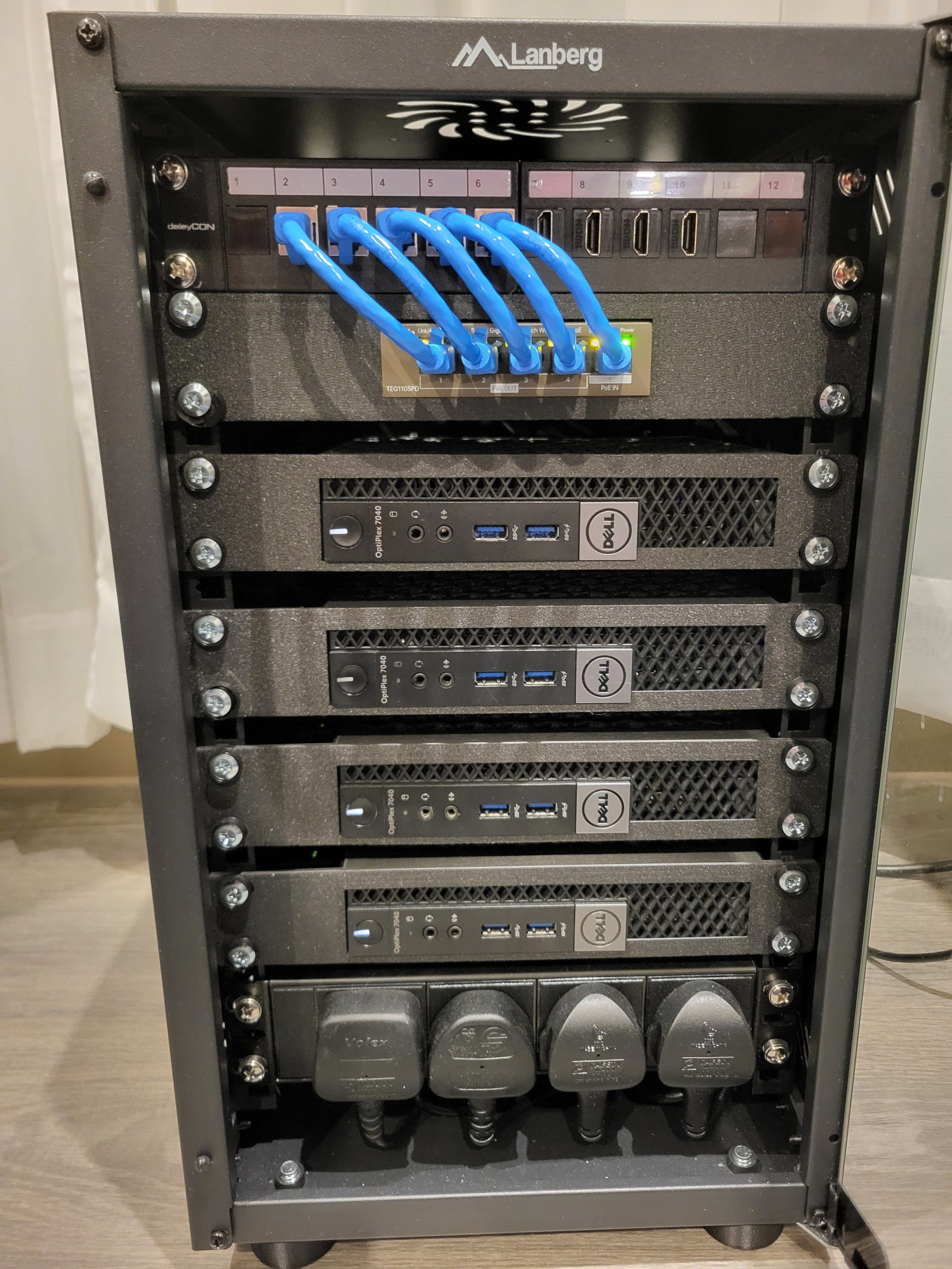
Behold, my homelab:
Bill of Materials
*  4 x Dell Optiplex 7040 Micro PCs         = £ 759.96
*  1 x Lanberg WF10-2309-10B cabinet        = £  49.85
*  1 x 4-way PDU                            = £  45.67
* 10 x ethernet cables                      = £  32.36
*  8 x deleyCON ethernet keystone modules   = £  24.34
*  1 x Tenda TEG1105PD switch               = £  20.26
*  2 x 1kg PLA filament                     ~ £  20.00
*  1 x deleyCON 12-port modular patch panel = £  18.72
*  1 x Tenda PoE30G-AT PoE injector         = £  15.67
* 20 x M6 cage nuts and screws              = £  13.36
*  4 x HDMI cables                          = £   8.69
*  5 x HDMI keystone modules                = £   7.80
* 10 x M10 35 mm screws                     = £   7.61
* 30 x keystone blanking plates             = £   4.56
======================================================
       Grand total                          = £1028.85
Closing remarks
Phew, that was a long write up. The entire process, from making the first order to completing the build took ~40 days, in between work and travel. I learned a lot. I have to say my favorite part was modelling the mounts. That’s going to be a core memory for both my wife and myself. We had a lot of fun!
As usual, if you have any comments, suggestions, or spot any mistakes, please let me know.
Hope you enjoyed this post. Until next time!
Intel Core i5-6500T, rated at only 35 W TDP. Full specs are here.↩︎
I found this schematic particularly useful, especially when designing rack mounts.↩︎
In its simplest form, a glorified extension cord that can fit in the rack.↩︎
Examples of these are brush strip panels, which allow cables to be pulled through but prevent air and dust from coming in, and panels with extruding D-ring hooks, which are used to hold and organise messy cables.↩︎
Specifications can be found on MikroTik website.↩︎
Unlike Dell PowerEdge servers, Dell Optiplex PCs do not have an onboard LOM controller. However, Intel AMT does provide a fair deal of management options, including remote KVM and serial-over-LAN. Still, I feel like having the option to physically connect to video output without having to disassemble the cabinet is nice.↩︎
There is a similar rack mount offering from racknex.com, but at a very steep price point.↩︎