NAT Woes in Oracle Cloud Land
Setting up NAT on a Compute Instance
Posted on 2022-02-12
The code referenced in this post is available freely here.
Last year Oracle announced its Always Free offering for Oracle
Cloud (OCI). It’s quite awesome, really: plenty of horsepower for free, with focus on
Ampere ARM instances. You can beef up a single Ampere instance up to 4 vCPUs
and 20 GiB of RAM, or distribute that quantity between multiple instances. And
you get two tiny VM.Standard.E2.1.Micro x86 instances on top of that1.
About the same time, I was looking into open-source versions of internal tools
used at Google, specifically Blaze vs. Bazel and Borg vs. k8s. I needed
a couple of VMs to test stuff out, so I signed up.
After some experimentation, I came up with the following (I’m using OCI terms here, but I assume there are similar concepts with other cloud providers):

There’s one OCI Virtual Cloud Network (VCN) with two OCI Subnets: Frontend and Backend. Traffic is routed between all subnets in VCN transparently. Subnet CIDRs must not overlap. OCI Compute Instances in a subnet get assigned a private IP belonging to that subnet by DHCP.
I want to use the instance in the Frontend subnet as a) as a singular frontend instance, so that I can expose whatever API I am trying out to the rest of the world, and b) a bastion host, for SSH access to the rest of the cluster. To be able to do this, the frontend instance needs to be assigned a public IP address. On the other hand, I want my Backend subnet to be isolated, meaning strict access control and no public IPs.
This can be done by OCI Routing Tables. These define how traffic that is
crossing VCN boundary is routed. I need two routing tables, one for each
subnet. Frontend routing table routes 0.0.0.0/0 to OCI Internet Gateway,
which allows bidirectional communication with the outside world. Backend
routing table, on the other hand, routes 0.0.0.0/0 to OCI NAT Gateway, which,
as name implies, enables outgoing traffic to the outside world, but prevents
the outside world from accessing any resources within by performing network
address translation.
NAT Gateway no longer available?
It seems that Oracle has recently disabled NAT gateways for Always Free
accounts. I became aware of this as I started getting Error Message: NAT gateway limit per VCN reached during terraform apply. And surely enough, I
found out that the limit for NAT gateways in the UI had been changed to 0:
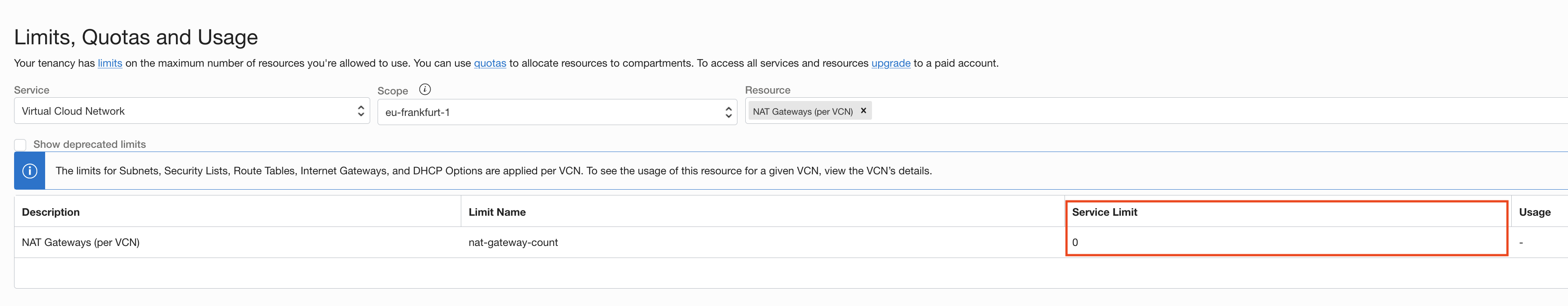
My Compute Instances in the Backend subnet now had no way to access the Internet. The frontend instance still had access to the Internet, though. Could I set up that node to perform NAT for all nodes in the Backend subnet?
It appears that it is, indeed, possible to set up OCI routing tables so that
they route 0.0.0.0/0 to a single IP address. The setup involves bringing up
a secondary VNIC, assigning it a dedicated IP address, and using that IP (its
OCID, specifically) as network_entity_id
in the route table rule.
Let’s get started, then.
Setting up frontend instance for NAT
Infrastructure changes
I am using Terraform to manage my tiny
cloud. Changing the infrastructure boils down to making changes to
.tf files, and then running terraform apply to perform changes to.
I start by attaching another VNIC (virtual NIC) to the frontend instance. This
VNIC will be assigned another IP address in the Frontend subnet, and this
address will be used to route 0.0.0.0/0 traffic in the Backend subnet.
resource "oci_core_vnic_attachment" "nat_gateway_vnic" {
  create_vnic_details {
    display_name = "NAT VNIC"
    # Only one public IP may be assigned per instance, and it's already assigned
    # to the first VNIC.
    assign_public_ip = false
    # I picked 192.168.1.250 for NAT IP. This will be set as primary VNIC IP.
    private_ip = var.nat_frontend_ip
    # Attach VNIC to Frontend subnet.
    subnet_id = oci_core_subnet.frontend.id
    # Don't drop forwarded packets.
    skip_source_dest_check = true
  }
  # Attach to the frontend instance.
  instance_id = oci_core_instance.tengu.id
}

# Fetch private IPs of secondary VNIC (yes, there can be more than one, but we
# are only interested in primary IP address).
data "oci_core_private_ips" "nat_vnic_ip_addresses" {
  vnic_id = oci_core_vnic_attachment.nat_gateway_vnic.vnic_id
}
Next, I set up routing table for the Backend subnet so it routes 0.0.0.0/0
traffic to NAT frontend IP:
resource "oci_core_route_table" "backend_route_table" {
  compartment_id = oci_identity_compartment.always_free.id
  vcn_id         = oci_core_virtual_network.vcn.id
  route_rules {
    # Route 0.0.0.0/0 to primary private IP of NAT gateway VNIC.
    destination       = var.all_cidr
    destination_type  = "CIDR_BLOCK"
    network_entity_id = data.oci_core_private_ips.nat_vnic_ips.private_ips[0].id
  }
}

resource "oci_core_subnet" "backend" {
  # Use backend routing table for Backend subnet.
  route_table_id = oci_core_route_table.backend_route_table.id
  # ... (omitted for brevity)
}
Finally, I have to allow ingress traffic coming from Backend subnet in OCI Security Lists that apply to Frontend subnet. Security Lists are used to set up ingress and egress traffic rules on a subnet, or even VNIC, level. For example, if you want to allow ingress SSH traffic on a specific instance, you both need to:
- add a corresponding ingress security rule to the Security List used for that subnet (or VNIC), and
- set up whatever firewall you have on the instance to allow same ingress traffic.
And even though traffic is routed between subnets in the same VCN automatically, i.e. you don’t need explicit entries in OCI Route Tables for routing inter-subnet traffic, Security Lists still apply nonetheless2.
Here’s a snippet that allows ingress traffic from the Backend subnet:
resource "oci_core_security_list" "public" {
  compartment_id = oci_identity_compartment.always_free.id
  vcn_id         = oci_core_virtual_network.vcn.id

  display_name = "Public"

  # Allow all egress.
  egress_security_rules {
    stateless        = false
    destination      = var.all_cidr
    destination_type = "CIDR_BLOCK"
    protocol         = "all"
  }

  # Allow all ingress for Backend subnet (for NAT).
  ingress_security_rules {
    stateless = false
    # This is 192.168.0.0/24.
    source = var.backend_cidr
    source_type = "CIDR_BLOCK"
    protocol = "all"
  }
  # ... (omitted for brevity)
}
After applying these changes, I can move on to configuring the frontend instance.
Enabling NAT on the frontend instance
First of all, IP forwarding needs to be enabled on the frontend instance:
sysctl -w net.ipv4.ip_forward=1Next, I add a POSTROUTING rule that masquerades packets, which will replace
source IP address of packets leaving primary interface enp0s3 with IP address
of the interface (192.168.1.119) on their way out:
firewall-cmd --permanent --direct --add-rule ipv4 nat POSTROUTING 0 \
  -o enp0s3 -j MASQUERADE
Since default policy in the FORWARD iptables chain is accept, I don’t really need to
add explicit rules that allow forwarded traffic from enp1s0 (secondary
VNIC) to enp0s3 (primary VNIC), but I’m listing the commands here for
completeness:
firewall-cmd --permanent --direct --add-rule ipv4 filter FORWARD 0 \
  -i enp1s0 -o enp0s3 -m state --state RELATED,ESTABLISHED -j ACCEPT
firewall-cmd --permanent --direct --add-rule ipv4 filter FORWARD 0 \
  -i enp1s0 -o enp0s3 -j ACCEPT
firewall-cmd --reload
At some point I realise I can enable masquerading with firewall-cmd, and
that this will automatically take care of setting net.ipv4.ip_forward.
However, I cannot see the masquerade rule in the POSTROUTING iptables chain now. Hmm,
the more I read about firewall-cmd the more I dislike it. At some point I
realize that the changes it makes are not reflected in iptables, but can be
seen with nft list table ip firewalld. Having only ever used iptables, I realize I am
out of my depth here, and I decide to leave it at that.
firewall-cmd --permanent --zone public --add-interface enp0s3
firewall-cmd --permanent --zone public --add-masquerade
firewall-cmd --reload
Phew, I think this is it. Time to test it out.
Almost there, but not quite yet
I SSH to one of backend instances, and run ping www.google.com.
PING www.google.com (142.250.185.174) 56(84) bytes of data.Nothing. At least the instance is able to resolve the address3.
Okay, so what is going on here? I first check if I am seeing any of these
packets at all on the NAT interface. I fire up tcpdump on the frontend
instance:
# on the backend instance
ping -c5 www.google.com
# on the frontend instance
tcpdump -nni enp1s0 -w ping-in.tcpdump icmp
Great, I see 5 packets come in:
dropped privs to tcpdump
tcpdump: listening on enp1s0, link-type EN10MB (Ethernet), capture size 262144 bytes
^C5 packets captured
5 packets received by filter
0 packets dropped by kernel
Let’s inspect them (timestamps eluded for brevity):
tcpdump -nnr ping-in.tcpdumpreading from file ping.tcpdump, link-type EN10MB (Ethernet)
IP 192.168.0.70 > 142.250.185.174: ICMP echo request, id 13059, seq 1, length 64
IP 192.168.0.70 > 142.250.185.174: ICMP echo request, id 13059, seq 2, length 64
IP 192.168.0.70 > 142.250.185.174: ICMP echo request, id 13059, seq 3, length 64
IP 192.168.0.70 > 142.250.185.174: ICMP echo request, id 13059, seq 4, length 64
IP 192.168.0.70 > 142.250.185.174: ICMP echo request, id 13059, seq 5, length 64Okay, so the frontend instance receives ICMP packets on enp1s0. Let’s see
if there is any ICMP traffic on primary interface:
# on the backend instance
ping -c5 www.google.com
# on the frontend instance
tcpdump -nni enp0s3 -w ping-out.tcpdump icmp
# on the backend instance
^C0 packets captured
0 packets received by filter
0 packets dropped by kernelHmm. It seems that the packets get dropped at some point after they are received
at the NAT interface. The FORWARD iptables chain does not show any change in
packet count. This is where I would expect to see a change after a packet has
been routed. However, when I look at the NAT table with iptables -t nat -nvL,
I notice that packet counter does increase for the PREROUTING chain:
Chain PREROUTING (policy ACCEPT 325 packets, 25368 bytes)
                                ^^^ this number increases by 5
It changes in increments of 5, once for each ICMP packet. Prerouting happens
before actual routing decision is made. Based on the routing decision, packets
go to either the INPUT or the FORWARD chain. And I know that neither of
those two chains sees any ICMP packets4. Therefore, packets must be
discarded at some point in between.
I don’t really know a lot about what happens at this point in the network
stack, so I look at netstat -s to see if I could spot any interesting counter
changes (watch -d -n1 helps a lot). And, sure enough, I do notice that one of
various displayed stats is changing in increments of 5 every time I run the
ping command:
IPReversePathFilter: 325A bit of googling tells me that this increments every time a packet gets
dropped due to reverse-path filtering. RP filtering prevents hosts from
forwarding packets that are not really routable – for example, a packet from
192.168.0.0/16 received on an Internet-facing interface will be dropped.
Reading a bit about it here, I
check to see if it is active on the frontend instance with sysctl net.ipv4.conf.all.rp_filter:
net.ipv4.conf.all.rp_filter = 1Aha! RP filtering is enabled in Strict mode, meaning that if the interface that the packet arrived from is not the best route for source address, the packet will be dropped. Let’s try relaxing it to Loose mode, which should allow packets that can be routed back to any other interface:
sysctl -w net.ipv4.conf.all.rp_filter=2I repeat my ping experiment, start capturing traffic again with tcpdump -nni enp0s3 icmp on primary interface, and – success (timestamps eluded for brevity):
IP 192.168.1.119 > 142.250.185.174: ICMP echo request, id 6750, seq 1, length 64
IP 142.250.185.174 > 192.168.1.119: ICMP echo reply, id 6750, seq 1, length 64
IP 142.250.185.174 > 192.168.0.70: ICMP echo reply, id 6750, seq 1, length 64
IP 192.168.1.119 > 142.250.185.174: ICMP echo request, id 6750, seq 2, length 64
IP 142.250.185.174 > 192.168.1.119: ICMP echo reply, id 6750, seq 2, length 64
IP 142.250.185.174 > 192.168.0.70: ICMP echo reply, id 6750, seq 2, length 64
IP 192.168.1.119 > 142.250.185.174: ICMP echo request, id 6750, seq 3, length 64
IP 142.250.185.174 > 192.168.1.119: ICMP echo reply, id 6750, seq 3, length 64
IP 142.250.185.174 > 192.168.0.70: ICMP echo reply, id 6750, seq 3, length 64
IP 192.168.1.119 > 142.250.185.174: ICMP echo request, id 6750, seq 4, length 64
IP 142.250.185.174 > 192.168.1.119: ICMP echo reply, id 6750, seq 4, length 64
IP 142.250.185.174 > 192.168.0.70: ICMP echo reply, id 6750, seq 4, length 64
IP 192.168.1.119 > 142.250.185.174: ICMP echo request, id 6750, seq 5, length 64
IP 142.250.185.174 > 192.168.1.119: ICMP echo reply, id 6750, seq 5, length 64
IP 142.250.185.174 > 192.168.0.70: ICMP echo reply, id 6750, seq 5, length 64
I see there are 15 packets in total:
5 ICMP request packets from
192.168.1.119, which is the IP address of primary interfaceenp1s0, that have been forwarded from secondary interfaceenp0s1. The source IP address was properly rewritten (masqueraded). So far so good.5 ICMP reply packets from the remote server that follow each ICMP request packet, with destination set to the IP address of primary VNIC, again
192.168.1.119. Destination address will be de-masqueraded to source IP address of the original ICMP request packet that was received on secondary VNIC (192.168.0.70).5 ICMP reply packets… wait… why do I see another 5 reply packets here? These appear immediately after first ICMP reply packet. Destination address was indeed rewritten to
192.168.0.22, but these packets should not appear on primary interface (enp0s3), but on secondary instead (enp1s0).
This obviously has something to do with routing. So I take a look at the
routing table with ip route:
default via 192.168.1.1 dev enp0s3
default via 192.168.1.1 dev enp0s3 proto dhcp metric 100
169.254.0.0/16 dev enp0s3 scope link
169.254.0.0/16 dev enp0s3 proto dhcp scope link metric 100
192.168.1.0/24 dev enp0s3 proto kernel scope link src 192.168.1.119
192.168.1.0/24 dev enp0s3 proto kernel scope link src 192.168.1.119 metric 100
192.168.1.0/24 dev enp1s0 proto kernel scope link src 192.168.1.250 metric
But of course! There is no entry for Backend subnet 192.168.0.0/24. So this
gets matched to default route, which uses primary interface enp0s3. I can fix this easily:
ip route add 192.168.0.0/24 via 192.168.1.1 dev enp1s0This will route traffic destined for Backend subnet to default gateway
192.168.1.1 but on secondary interface enp1s0. Traffic between OCI
subnets is routed via default gateway – there is no direct route to Backend
subnet from my frontend instance, it has to go through default gateway (do note
that secondary VNIC is within the same Frontend subnet as the primary VNIC).
However, now the packets that need to go to Backend subnet will get appear on
secondary interface enp1s0, and the gateway will route these packets
correctly to their source in Backend subnet.
Finally, pinging from backend instance works as expected, curl works fine,
and, most importantly, I can install packages via dnf on backend instances
now.
Open questions
I still don’t understand a couple of things here:
After adding a static route, I set RP filtering to Strict again, just for fun, and no forwarded packets were being filtered out. I guess this is because packets that originated in Backend subnet can now be routed back on the same interface they came from (
enp1s0).Secondary VNIC on the frontend instance is connected to Frontend subnet. Could I have simply forwarded packets coming from Backend subnet to that same interface, masquerading them with
enp1s0IP address (192.168.1.250)? Default gateway is reachable on that interface, obviously, so this seems… plausible?ocidis a daemon that sets up secondary VNIC during boot. I looked its logs, and it apparently creates a new routing table calledort3during startup:ip route add default via 192.168.1.1 dev enp1s0 table ort3 ip rule add from 192.168.1.250 lookup ort3This table contains only one route, the default one, which is similar to the route I had to add to main routing table. In addition, this routing table is only used for packets coming from
192.168.1.250. I wonder if this proves that my previous point was how all of this was intended to work out?firewalldis a great mystery to me. On the surface, it is easy to use, and I see motivation behind it. But in order to grok it fully, I apparently need to understandnftablesas well. How does it interact withiptables? There are only 4iptablestables:nat,mangle,filterandraw, but there are many morenftablestables. What is the difference betweenipandinettables? So many questions.
I hope this was an interesting read. Please shoot me an email if this was useful for you, to let me know about all the mistakes I made, or if I missed a painfully obvious thing.
There’s a catch though – you can only spin up to 4 VMs because boot disks can’t be smaller than 50 GiB, so 4 instances with boot disks will fill up your Always Free 200 GiB block volume storage quota.↩︎
It took me couple of hours of banging my head against the wall to figure out that the reason I was loosing every TCP packet sent out from a backend instance was because traffic was being filtered by Security Lists in the Frontend subnet.↩︎
Oracle provides DNS by default for all instances, regardless of whether they are in a subnet which has Internet gateway or not. Corresponds to
VCNLocalPlusInternetoption inDhcpDnsOptionobject.↩︎Because of background traffic, probably caused by Oracle’s background services, for the
INPUTchain I could not rely on total packet counter. Instead, I created a rule that matched only ICMP packets coming from backend subnet. This confirmed my suspicion that no ping packets were arriving at theINPUTchain, as this counter remained at zero.↩︎